Wiring up switch in place of key/ignition
#1
 06-01-2012, 01:54 AM


Join Date: Jun 2011
Posts: 592
First off, I'm very confused on the differences in these switches and my searching of Google and the forums for what switch people used for wiring up the ignition has yielded 3 different results.
S301 NKK Switches | 360-1896-ND | DigiKey
http://www.digikey.com/scripts/DkSea...8&y=10&cur=USD
S32 NKK Switches | 360-2085-ND | DigiKey
One switch is 3PST, another is SPST and the other is 3PDT. I have no idea what the differences are or which one I need to use. Easiest application possible would be nice. I have an 06 klx.
Any idea on the differences in the 3 are in the context of using them on the klx? I know there is a 100 ohm resistor that has to be put inline for the ECU to function properly and actually give spark.
Thanks
#2
06-01-2012, 03:05 AM

jhoffy,
I don't know which one is best for your bike but I can tell you what the difference is between the three. If you know the circuit, this may help you decide.
3PST is three poles, single throw. The three poles (3P) allows you to switch three separate circuits with one switch. The single throw (ST) allows only on or off.
SPST is a single pole single throw. The single pole allows you to switch only one circuit with the switch. The single throw is as described above.
The 3PDT is a three pole double throw. The three pole is as described in the 3P above. The double pole (DT) allows you to make the switch operate separate circuits in either position. For example, toggling the switch to the left could turn on a green light but switching it to the right could turn on a red one instead. If you only had the green light, no connection on the other side acts as a single throw.
Hope this helps your decision. To be sure, a schematic diagram would help.

#4
06-01-2012, 03:25 AM

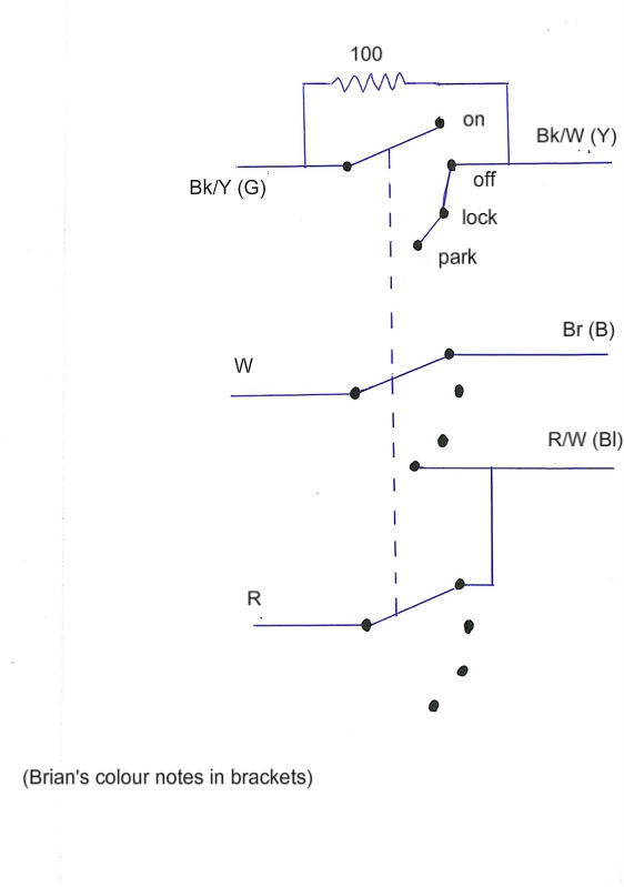
The 09 wiring diagram has the following connections:
OFF&LOCK: BK/Y TO BK/W
ON: W TO BR, AND R TO R/W
I am not so certain why there are connections for the off position, maybe someone else knows.
I would recommend getting a 3PDT, use one pole for the off, use the two other poles for the ON connections.
But the 06 maybe different, but without a wiring diagram, your on your own.
See the wiring diagram above, same deal.
Last edited by durielk; 06-01-2012 at 03:27 AM.
#5
06-01-2012, 03:36 AM
Join Date: Jun 2011
Posts: 592
Here is a wiring diagram from an 07 which is the same as my 06.
http://klx250s.suncup.net/Misc%20Doc...ng-diagram.PDF
http://klx250s.suncup.net/Misc%20Doc...ng-diagram.PDF

#7
06-01-2012, 03:41 AM
360-1908-ND looks like the switch you would need based on your diagram. If your diagram is correct, you need 3PDT with positions on-off-on. None of the ones you listed fit that description. The part number I listed does. It is a 25 amp switch though. That will work electrically for the bike but may be physically larger or more expensive than something around 6 to 15 amps.
The way it would work is that you would switch it to the left to the on position. Switched to the middle would kill the bike. Switched to the right would put it into the park position.
The way it would work is that you would switch it to the left to the on position. Switched to the middle would kill the bike. Switched to the right would put it into the park position.
#8
06-01-2012, 03:44 AM
Join Date: Jun 2011
Posts: 592
360-1908-ND looks like the switch you would need based on your diagram. If your diagram is correct, you need 3PDT with positions on-off-on. None of the ones you listed fit that description. The part number I listed does. It is a 25 amp switch though. That will work electrically for the bike but may be physically larger or more expensive than something around 6 to 15 amps.
The way it would work is that you would switch it to the left to the on position. Switched to the middle would kill the bike. Switched to the right would put it into the park position.
The way it would work is that you would switch it to the left to the on position. Switched to the middle would kill the bike. Switched to the right would put it into the park position.
Edit: I lied, the first diagram is from an 06.
Last edited by jhoffy22; 06-01-2012 at 03:50 AM.
#9
06-01-2012, 04:13 AM
The third position is "locked" not park & it is the same as "off"
Actually you do not list the year bike you have until you post later you have an 06. The 1st wiring diagram you say is an 09, which is not the same as the 07. Do you have a "park position"? My 07 does not. If your removing a keyed switch, do you really want a "park" position?
Last edited by durielk; 06-01-2012 at 04:22 AM.
#10
06-01-2012, 06:44 AM
Gents...been through this one and my setup works.
I believe the diagram may be for an Aus bike, '06 or newer (duh) with a park circuit. My '06 doesn't have a park circuit. But remove the park portion and it's the same. With the double throw switch, think of it as on-on, or perhaps A-B (where some circuits are connected in 'A' and others in 'B' positions). I believe a park circuit would need a triple throw (on-off-on). My switch is a 3PDT I believe...it has a total of 9 pins. The double throw portion I think is for the security resistor circuit. But I'm not using it that way, and am only using 6 of the 9 pins (three in the middle & three on the bottom connected, three on the top are unused). I could have used a 3PST.
I believe the diagram may be for an Aus bike, '06 or newer (duh) with a park circuit. My '06 doesn't have a park circuit. But remove the park portion and it's the same. With the double throw switch, think of it as on-on, or perhaps A-B (where some circuits are connected in 'A' and others in 'B' positions). I believe a park circuit would need a triple throw (on-off-on). My switch is a 3PDT I believe...it has a total of 9 pins. The double throw portion I think is for the security resistor circuit. But I'm not using it that way, and am only using 6 of the 9 pins (three in the middle & three on the bottom connected, three on the top are unused). I could have used a 3PST.