
Another MotoPro fork valving question
#21
 02-06-2011, 12:54 PM

David, I owe you beer!  I'm going to try this again and I'll take pics of what I come up with.
We should document all of this this so it's easier on the next guy.
I'm going to try this again and I'll take pics of what I come up with.We should document all of this this so it's easier on the next guy.
#22
02-06-2011, 01:31 PM
#23
02-06-2011, 01:58 PM
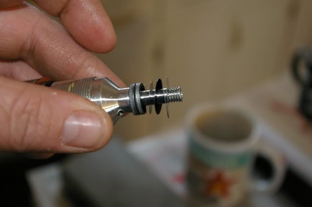
Here is the first stack, the high speed compression valving. The first 2 are just washers to elevate the stack. That's all. If I did it right, they start with the smallest shims and then get wider as you stack. I think the idea is for the edges to be flimsier so the pressure can blow the edges open easier and let fluid past.
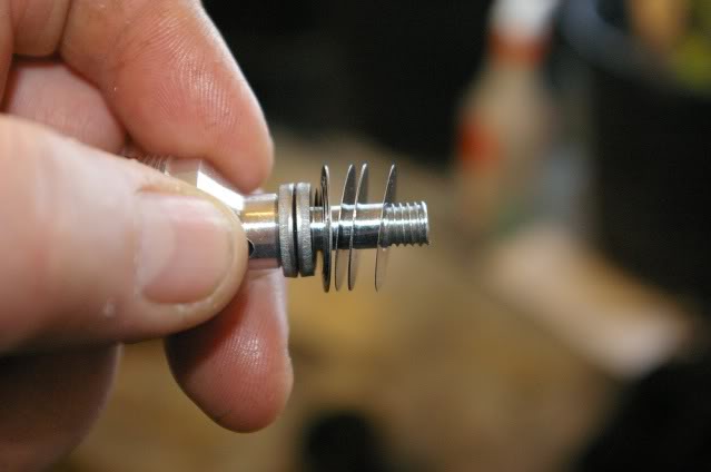
Here's the 2nd stack on top. This is the low speed compression valving. I put it directly on top of the other valving stack, starting with a 12mm shim, then going to the 17s, just like the destructions say.
Now they say to take the green disk and put it with the oval holes facing down. I assume they're talking about the holes on the tops of the boss and not the holes in the recesses because they both go from round to oval in different directions.
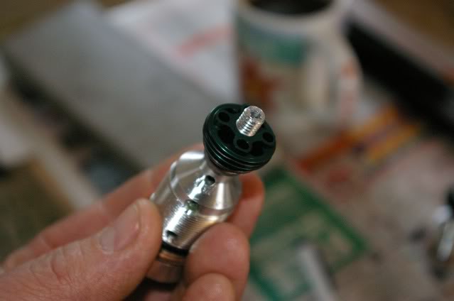
Now I need to study some pics and finger out this check valve on top. More pics to come.
I can hear the Chariots of Fire song playing in my head. You have to play this in the background while you're doing this.
http://www.youtube.com/watch?v=TYJzcUvS_NU
Here's the 2nd stack on top. This is the low speed compression valving. I put it directly on top of the other valving stack, starting with a 12mm shim, then going to the 17s, just like the destructions say.
Now they say to take the green disk and put it with the oval holes facing down. I assume they're talking about the holes on the tops of the boss and not the holes in the recesses because they both go from round to oval in different directions.
Now I need to study some pics and finger out this check valve on top. More pics to come.
I can hear the Chariots of Fire song playing in my head.
You have to play this in the background while you're doing this.http://www.youtube.com/watch?v=TYJzcUvS_NU
#24
02-06-2011, 02:46 PM
Maybe you know him, but maybe you find it useful
http://klxforum.suncup.net/viewtopic...1dbee&start=10
http://klxforum.suncup.net/viewtopic...1dbee&start=10
#25
02-06-2011, 03:14 PM
Thank you, brother TNC for posting this!
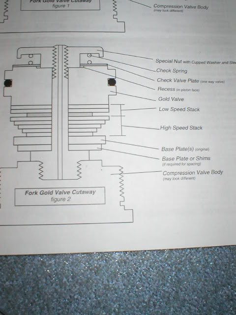
I see how this works now. There's recess on one side corresponding with boss on the other side and vice versa. From there we have 17mm shims laying flat on each side blocking off fluid flow. The ones on top are held down with spring pressure to give it some resistance bleeding back up hill. Now with fluid rushing down on it go into the recesses and hit the 17mm shims underneath that'll flex away, I'm assuming, and let the appropriate amount of fluid bleed past. Do I have this right? I think I'll do like David did and use 2 of the 17mm shims with the 8mm holes on each.
I see how this works now. There's recess on one side corresponding with boss on the other side and vice versa. From there we have 17mm shims laying flat on each side blocking off fluid flow. The ones on top are held down with spring pressure to give it some resistance bleeding back up hill. Now with fluid rushing down on it go into the recesses and hit the 17mm shims underneath that'll flex away, I'm assuming, and let the appropriate amount of fluid bleed past. Do I have this right? I think I'll do like David did and use 2 of the 17mm shims with the 8mm holes on each.
#26
02-06-2011, 03:25 PM
And here we are.
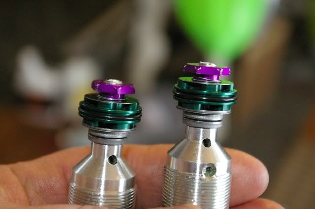
Locktite? It don't need no stinkin' locktite. Those threads are so tight it had me scared I was going to strip it out. I had to run the old nuts on and off about 10 times and put a small drop of Triflow on to keep it from galling and seizing together. I didn't torque anything, just got it home light snug. I'm not screwing around with that. It's on. It's home. It ain't coming apart under its own power.
Now to get the top shims on straight while tightening down the purple nuts was a little bit of a trick. I had to hold them up so they'd engage the nut. Here's what I did.
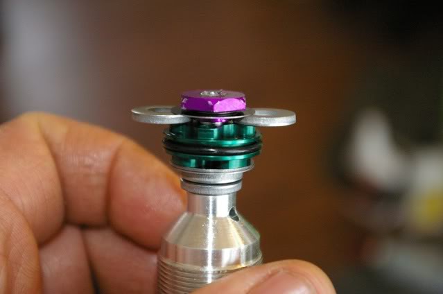
Guys, does it look like I did it right? I'm going to start tossing this thing back together soon.
Locktite? It don't need no stinkin' locktite. Those threads are so tight it had me scared I was going to strip it out. I had to run the old nuts on and off about 10 times and put a small drop of Triflow on to keep it from galling and seizing together. I didn't torque anything, just got it home light snug. I'm not screwing around with that. It's on. It's home. It ain't coming apart under its own power.
Now to get the top shims on straight while tightening down the purple nuts was a little bit of a trick. I had to hold them up so they'd engage the nut. Here's what I did.
Guys, does it look like I did it right? I'm going to start tossing this thing back together soon.

#28
02-06-2011, 07:59 PM
Well I'm late to today's game, but it looks like the 4th quarter and Feral D is driving in from the 5-yard line for a touchdown!
Obviously you're the only one who knows if you got the shim stack right, but that sure looks like the correct configuration to me. I notice those main valves are quite different from the Gold Valves, but the principle is the same. Good work!
I gotta say, however, that I'm glad I went with the Gold Valve setup. Those are the gayest colors on the valve and cupped washer nut that I've seen in awhile. OK, OK, I just had to throw some dirt in on top of what appears to be a very successful job...LOL!
#29
02-06-2011, 08:30 PM
Join Date: Jan 2010
Location: kootenay country BC Canada
Posts: 1,800