
Another MotoPro fork valving question
#11
 02-05-2011, 04:54 PM

All that said, it's obvious that if a couple of meatheads like David and FD could do the revalve with the written instructions from MP, it's obvious that a superior intellect like you will have no issue...LOL!

I love you guys.
#12
02-05-2011, 10:11 PM
Hey, this meat head ain't doing so hot with this. The directions aren't complete and without you guys helping me, I'd be screwed.
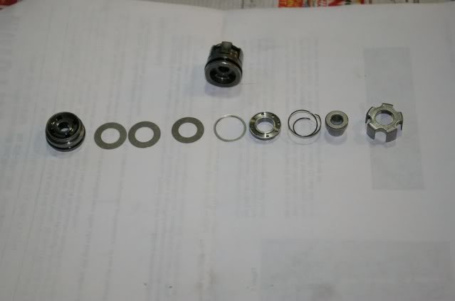
Ok. Here is the stock valve taken apart. and the other one not taken apart yet on top. What's what? Where are the 2 locator shims I start with? I got 3 shims the same size. Are those it? They don't locate anything. Other than that, there's not 2 of anything.
Ok. Here is the stock valve taken apart. and the other one not taken apart yet on top. What's what? Where are the 2 locator shims I start with? I got 3 shims the same size. Are those it? They don't locate anything. Other than that, there's not 2 of anything.
#13
02-05-2011, 10:37 PM
Now, in this kit of new parts I have 17mm shims. The problem is I got 2 different hole diameters and there's no mention of it anywhere what goes where.
I'm tempted to give up but I got the other valves taken apart and I'm not sure if I got the arrangement of the stock shims right. I'm tempted to send this back to John and get the kit from Race Tech.
I'm tempted to give up but I got the other valves taken apart and I'm not sure if I got the arrangement of the stock shims right. I'm tempted to send this back to John and get the kit from Race Tech.
#14
02-06-2011, 12:07 AM
FD, don't worry about the old stuff. Heck, it's been so long since I looked at mine, I can't figure it out anymore.
The new valving should be more logical. MP or RT kit, it's going to look more like my diagram I posted on that other thread here. Remember the order of your shim stack should match my diagram. The lowest stack is the highest speed pack, and the upper stack is low speed compression. There should be a smaller separating shim between the high and low speed stacks...my diagram clearly shows that. Stack the spacers for each pack in an ascending order from small to big. They are separated by that smaller separating shim.
In that diagram, picture the fork compressing. The oil is being forced from the top through the new piston valve, out of the large passages in the piston valve, and down on to the face of the shims. That oil pressure forces those shims open all the way down the length of the two stacks...if the pressure is great enough...which means the bump has to be big enough.
Your instructions should show 2 numbers for the shims. The tiny number with the decimal point is the thickness of the shim, and the bigger number is the diameter of the shim. Stack the shims as per your instructions from the bottom of the valve body starting with the high compression stack. The smallest shim goes first, followed consistently by bigger or stronger shims as you stack the shims on the valve body. Now, I also used a cheap $15 digital vernier caliper that I have to verify what shims I was handling, as it's easy to lay a shim down on the bench and then forget which one it was...and that's without the help of your friend in that other picture, Seagram's VO...LOL!
So on your valve body you should start with a base plate, followed by the high speed stack, followed by the separating shim, followed by the low speed stack, and then the main, new piston valve. On top of the valve there should be a check valve plate with a spring. On top of that there is either a cupped nut and sleeve or a supplied regular looking nut that caps everything off. Make sure that check valve plate under the spring can move up and down against that spring.
Your instructions may already say all this, but maybe if you have specific questions and can post a pic, I'll bet we can walk you through it.


#17
02-06-2011, 04:20 AM
FD, don't worry about the old stuff. Heck, it's been so long since I looked at mine, I can't figure it out anymore.
The new valving should be more logical. MP or RT kit, it's going to look more like my diagram I posted on that other thread here. Remember the order of your shim stack should match my diagram. The lowest stack is the highest speed pack, and the upper stack is low speed compression. There should be a smaller separating shim between the high and low speed stacks...my diagram clearly shows that. Stack the spacers for each pack in an ascending order from small to big. They are separated by that smaller separating shim.
In that diagram, picture the fork compressing. The oil is being forced from the top through the new piston valve, out of the large passages in the piston valve, and down on to the face of the shims. That oil pressure forces those shims open all the way down the length of the two stacks...if the pressure is great enough...which means the bump has to be big enough.
Your instructions should show 2 numbers for the shims. The tiny number with the decimal point is the thickness of the shim, and the bigger number is the diameter of the shim. Stack the shims as per your instructions from the bottom of the valve body starting with the high compression stack. The smallest shim goes first, followed consistently by bigger or stronger shims as you stack the shims on the valve body. Now, I also used a cheap $15 digital vernier caliper that I have to verify what shims I was handling, as it's easy to lay a shim down on the bench and then forget which one it was...and that's without the help of your friend in that other picture, Seagram's VO...LOL!
So on your valve body you should start with a base plate, followed by the high speed stack, followed by the separating shim, followed by the low speed stack, and then the main, new piston valve. On top of the valve there should be a check valve plate with a spring. On top of that there is either a cupped nut and sleeve or a supplied regular looking nut that caps everything off. Make sure that check valve plate under the spring can move up and down against that spring.
Your instructions may already say all this, but maybe if you have specific questions and can post a pic, I'll bet we can walk you through it.
The new valving should be more logical. MP or RT kit, it's going to look more like my diagram I posted on that other thread here. Remember the order of your shim stack should match my diagram. The lowest stack is the highest speed pack, and the upper stack is low speed compression. There should be a smaller separating shim between the high and low speed stacks...my diagram clearly shows that. Stack the spacers for each pack in an ascending order from small to big. They are separated by that smaller separating shim.
In that diagram, picture the fork compressing. The oil is being forced from the top through the new piston valve, out of the large passages in the piston valve, and down on to the face of the shims. That oil pressure forces those shims open all the way down the length of the two stacks...if the pressure is great enough...which means the bump has to be big enough.
Your instructions should show 2 numbers for the shims. The tiny number with the decimal point is the thickness of the shim, and the bigger number is the diameter of the shim. Stack the shims as per your instructions from the bottom of the valve body starting with the high compression stack. The smallest shim goes first, followed consistently by bigger or stronger shims as you stack the shims on the valve body. Now, I also used a cheap $15 digital vernier caliper that I have to verify what shims I was handling, as it's easy to lay a shim down on the bench and then forget which one it was...and that's without the help of your friend in that other picture, Seagram's VO...LOL!
So on your valve body you should start with a base plate, followed by the high speed stack, followed by the separating shim, followed by the low speed stack, and then the main, new piston valve. On top of the valve there should be a check valve plate with a spring. On top of that there is either a cupped nut and sleeve or a supplied regular looking nut that caps everything off. Make sure that check valve plate under the spring can move up and down against that spring.
Your instructions may already say all this, but maybe if you have specific questions and can post a pic, I'll bet we can walk you through it.
Last edited by Feral Donkey; 02-06-2011 at 04:25 AM.
#18
02-06-2011, 04:42 AM
On the RT diagram, you'll see the base plate as the first item stacked on the valve body...unless...you end up needing to stick some of your old shims under the base plate to have the final nut clearance at the top of this whole shebang come out properly. The "base plate" was with the old valving...according to my directions...and is basically a large washer. If I'd done mine a week ago, maybe I could remember exactly what it looked like. I do know this...if there wasn't a useable base plate in my OEM stack, RT sent a base plate washer with the kit. You have to have a base plate of some kind that at least exceeds the diameter of the first shim that makes contact with it, or you'll throw the damping off completely because it will let that first shim it contacts bend, allowing more oil flow and less damping. If you think a bit about the dynamics that are going on here, it makes more sense.
Maybe it would help if you show a pic of the MP parts laid out, and perhaps I can see a supplied base plate in the mix.
Maybe it would help if you show a pic of the MP parts laid out, and perhaps I can see a supplied base plate in the mix.
#20
02-06-2011, 12:29 PM

Don't worry I will help if I can. I will even send you my phone # if needed.
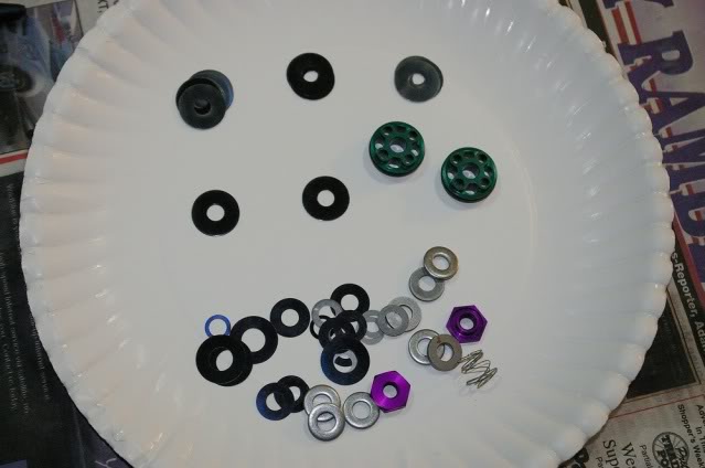
I put TWO of the small Thick washers on to locate the stack whole setup so the nut gets a full thread.
Then the shim stacks etc.
The four washers with the bigger hole are the check valve that go on the purple nut. I used 2 per side. and NO there is nohting at all in the instructions about them. 15 years as a forklift mechanic (hydraulics) helped me figure that one out.
I did not use a torque wrench or blue locktite. I used my head...,,,, NOT disagreeing with the instructions, just doing things my way.
Thanks for the clue about shifts, this explains the 2:44 am post when I was in la la land.
You are inches from done. You DO need a way to tell which 17mm shim is thicker, the rest are all .10mm
I used NOTHING from the old valve.
My kit was missing a 12mm shim so I used an 11mm. PM sent to FD
David